Nest Thermostat Wiring For Heat Pump
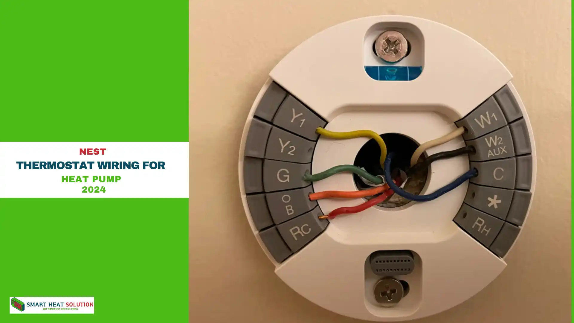
Before you start wiring your Nest thermostat, there are a few important steps to follow.
First, ensure that your thermostat is compatible with your existing system. You can use the compatibility checker tool available here.
Once you’ve confirmed compatibility, turn off your HVAC system to ensure your safety and protect your equipment from damage. Typically, you can switch off most air handlers at the circuit breaker.
If you’re not comfortable with DIY projects, we recommend seeking professional assistance. However, if you’re handy, this installation should take you about 20-30 minutes.
In this guide, you’ll learn about:
- Preparing your Nest thermostat for wiring
- Wiring diagrams for furnaces and air conditioners
- Nest wiring diagrams for heat pumps
- Wiring diagrams for variable speed fans
Introduction to Nest Thermostat and Heat Pump Systems
Before diving into the wiring details, it’s important to understand the basics.
The Nest Thermostat is an intelligent device that learns your heating and cooling preferences, making automatic adjustments and allowing remote control through a mobile app.
Heat pump systems, on the other hand, are energy-efficient HVAC units that provide both heating and cooling by transferring heat between indoor and outdoor spaces.
Understanding the Basics of Nest Thermostat Wiring
Wiring a Nest Thermostat to a heat pump system may seem intimidating, but breaking it down into manageable steps simplifies the process. This section outlines essential information, including compatibility, required components, and key wiring steps.
Compatibility with Heat Pump Systems
Compatibility is crucial when wiring a Nest Thermostat for a heat pump. Fortunately, Nest devices are compatible with a wide range of HVAC systems, including heat pumps. To ensure compatibility, use Nest’s online compatibility checker or consult a professional.
Components Required for Wiring
Before you begin the wiring process, gather these essential components:
- Nest Thermostat
- Screwdriver
- Wire labels
- Smartphone or computer for setup and control
By following these guidelines, you can successfully wire your Nest Thermostat to your heat pump system, optimizing both energy efficiency and comfort in your home.
Preparing Your Nest Thermostat for Wiring
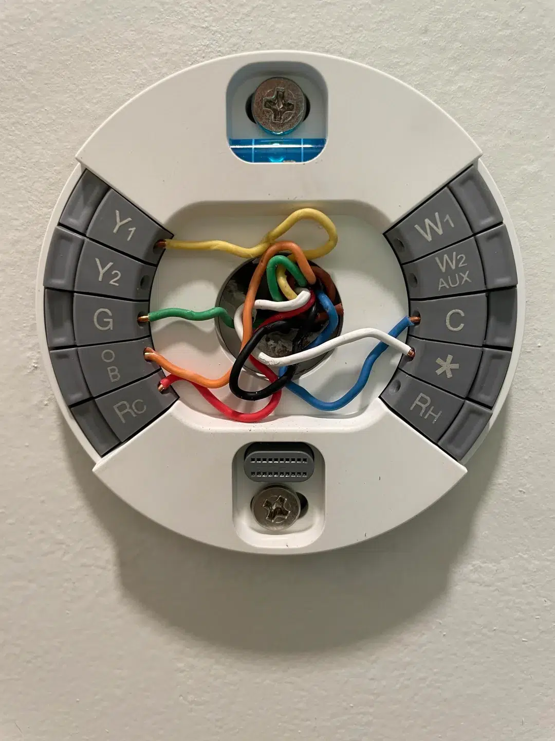
Installing a Nest thermostat can significantly enhance your home’s energy efficiency and comfort. Before diving into the installation process, it’s essential to prepare your thermostat properly. Here’s a detailed guide to ensure everything goes smoothly.
Step 1: Gather Your Materials
Before you begin, ensure that you have all the components included in the Nest thermostat box. Check your manual for a comprehensive list of accessories specific to your model. Different models may come with various mounting plates, screws, or additional connectors. Having everything on hand will streamline the installation process.
Step 2: Remove the Old Thermostat
Carefully detach the existing thermostat from the wall. Depending on the model, you might need to unscrew it from its mount. Take your time here to avoid damaging the wall or the thermostat itself. If there are any cables attached, handle them gently to prevent any disconnections.
Step 3: Inspect the Wiring
Examine the wires connected to your old thermostat. If you see thick wires labeled as 110V or 120V, this indicates that your system is incompatible with the Nest thermostat, which operates on low voltage (24VAC). Understanding the voltage of your system is crucial for a safe and effective installation.
Step 4: Document Existing Wiring
Before removing any wires, take a clear photo of the existing connections. This step is invaluable for reference later. Having a visual guide will help you reconnect the wires correctly, ensuring that you replicate the old setup as closely as possible.
Step 5: Check for Jumper Wires
Inspect the wiring for any jumper wires between connectors. Jumper wires are typically unnecessary for the Nest thermostat, as it automatically manages these connections. Remove any jumper wires carefully; keeping your setup clean will prevent confusion during installation.
Step 6: Prepare Wire Ends
Look closely at the ends of each wire. They should be straight and well-stripped, with at least ⅜ inch of exposed wire. Properly stripped wires are essential for secure connections, ensuring that your thermostat receives the necessary power without any interruptions.
Supported Wiring for Nest Thermostat Connectors
Conventional Connectors:
- Y1: Stage 1 compressor relay
- Y2: Stage 2 compressor relay, 2nd-speed fan relay
- G: Fan relay
- O/B: Not utilized
- Rc: 24VAC power from cooling transformer*
- W1: Stage 1 heat relay
- W2/AUX: Stage 2 heat relay
- C: 24VAC common wire
Heat Pump Connectors:
- Y1: Stage 1 compressor relay
- Y2: Stage 2 compressor relay
- G: Fan relay
- O/B: Changeover valve relay
- Rc: Not utilized
- W1: Stage 1 heat relay
- W2/AUX: Auxiliary heat relay
- C: 24VAC common wire
Note:
- *For conventional systems, additional stages may include W3 for Stage 3 heat, HUM for humidification, DEHUM for dehumidification, or 3rd-speed fan relay.
- *For heat pump systems, emergency heat (E), HUM, or DEHUM can also be connected to the W2/AUX terminals.
- Rh: 24VAC power from heating transformer*
Wiring Diagrams for Furnaces and Air Conditioners
To assist you further, here are wiring diagrams for different heating and cooling systems, including conventional setups and heat pumps. Remember, labeling the wires before removing them will make reconnection much easier.
Wiring Diagram for Stage 1 Furnace (4 Wire)
For a standard stage 1 furnace, the wiring typically consists of four wires connected to the following terminals:
- G: Fan Relay
- W1: Heat Relay (Stage 1)
- C: 24VAC Common Wire
- Rh: 24VAC Power from Heating Transformer
It’s vital to only connect wires that were previously attached to your old thermostat. This principle applies to all systems to prevent any potential electrical issues.
Wiring Diagram for Stage 2 Furnace (5 Wire)
For a stage 2 furnace, commonly referred to as a 5-wire thermostat setup, the wiring includes five connections:
- G: Fan Relay
- W1: Heat Relay (Stage 1)
- W2/AUX: Heat Relay (Stage 2) / Auxiliary Heat Relay
- C: 24VAC Common Wire
- Rh: 24VAC Power from Heating Transformer
Wiring Diagrams for Furnace Stages
Stage 3 Heating (6-Wire Diagram)
The wiring diagram for a stage 3 furnace consists of six wires connected to the following terminals: G, W1, W2, C, *, and Rh. This setup is also referred to as a 6-wire diagram.
- G: Fan Relay
- W1: Heat Relay (Stage 1)
- W2/AUX: Heat Relay (Stage 2)
- C: 24VAC Common Wire
- *: Additional connections for W3 (Stage 3 heat), E (emergency heat), HUM (humidification), DHUM (dehumidification), or a 3rd-speed fan relay
- Rh: 24VAC Power from Heating Transformer
For troubleshooting related to heating issues, check out our guide on why your Nest thermostat might blow cold air when set to heat.
First Stage Furnace with First Stage Air Conditioner (5-Wire Diagram)
For a first stage furnace combined with a first stage air conditioner, the wiring typically consists of five wires. It’s essential to differentiate this diagram from that of a second stage furnace. In a second stage diagram, you would see wires connected to both the W1 and W2 connectors. In this setup, you will find a wire connected to the Y1 connector and only one wire in the W1 connector.
- Y1: Compressor Relay (Stage 1)
- G: Fan Relay
- W1: Heat Relay (Stage 1)
- C: 24VAC Common Wire
- Rh: 24VAC Power from Heating Transformer
Second Stage Furnace with First Stage Air Conditioner (6-Wire Diagram)
This configuration, known as a 6-wire diagram for a stage 2 furnace with a single-stage compressor, also includes six wires, similar to the stage 3 setup. The key difference is that this diagram will have a wire connected to the Y1 connector, along with wires connected to both the W1 and W2 connectors.
- Y1: Compressor Relay (Stage 1)
- G: Fan Relay
- W1: Heat Relay (Stage 1)
- W2/AUX: Heat Relay (Stage 2)
- C: 24VAC Common Wire
- Rh: 24VAC Power from Heating Transformer
Second Stage Furnace with Second Stage Air Conditioner (7-Wire Diagram)
The 7-wire diagram for a second stage furnace paired with a second stage air conditioner includes connections for both compressor relay connectors (Y1 and Y2). Additionally, there are wires connected to both the W1 and W2 connectors.
- Y1: Compressor Relay (Stage 1)
- Y2: Compressor Relay (Stage 2)
- G: Fan Relay
- W1: Heat Relay (Stage 1)
- W2/AUX: Heat Relay (Stage 2)
- C: 24VAC Common Wire
- Rh: 24VAC Power from Heating Transformer
3rd Stage Furnace with 2nd Stage Air Conditioner (8-Wire Diagram)
A 3rd stage furnace paired with a 2nd stage air conditioner typically has eight wires connected. This configuration includes three separate wires going into the W1, W2, and W3 terminals. While the W3 connector might not be directly labeled, it is represented by the * connector in this setup.
- Y1: Compressor Relay (Stage 1)
- Y2: Compressor Relay (Stage 2)
- G: Fan Relay
- W1: Heat Relay (Stage 1)
- W2/AUX: Heat Relay (Stage 2)
- C: 24VAC Common Wire
- *: W3 (Stage 3 heat)
- Rh: 24VAC Power from Heating Transformer
1st Stage Furnace with 2nd Stage Air Conditioner (6-Wire Diagram)
A single-stage furnace paired with a 2nd stage air conditioner will typically have six wires. In this configuration, both the Y1 and Y2 connectors will be connected, but only the W1 connector should receive a wire.
- Y1: Compressor Relay (Stage 1)
- Y2: Compressor Relay (Stage 2), 2nd-speed fan
- G: Fan Relay
- W1: Heat Relay (Stage 1)
- C: 24VAC Common Wire
- Rh: 24VAC Power from Heating Transformer
Nest Pump Wiring Diagram
1st Stage Heat Pump (5-Wire Diagram)
For a single-stage heat pump, it’s essential to have a wire connected to the O/B terminal. This setup will typically consist of five wires, with one connected to the compressor relay for stage 1 (Y1).
- Y1: Compressor Relay (Stage 1)
- G: Fan Relay
- O/B: Heat Pump Changeover Valve
- Rc: 24VAC Power from Cooling Transformer
- C: 24VAC Common Wire
1st Stage Heat Pump with Auxiliary Heat (6-Wire Diagram)
A single-stage heat pump with auxiliary heat will have a total of six wires connected. In addition to the Y1 connector, you will also have the AUX connector connected.
- Y1: Compressor Relay (Stage 1)
- G: Fan Relay
- O/B: Heat Pump Changeover Valve
- Rc: 24VAC Power from Cooling Transformer
- AUX: Auxiliary Heat Relay
- C: 24VAC Common Wire
1st Stage Heat Pump with Auxiliary Heat and Emergency Heat (7-Wire Diagram)
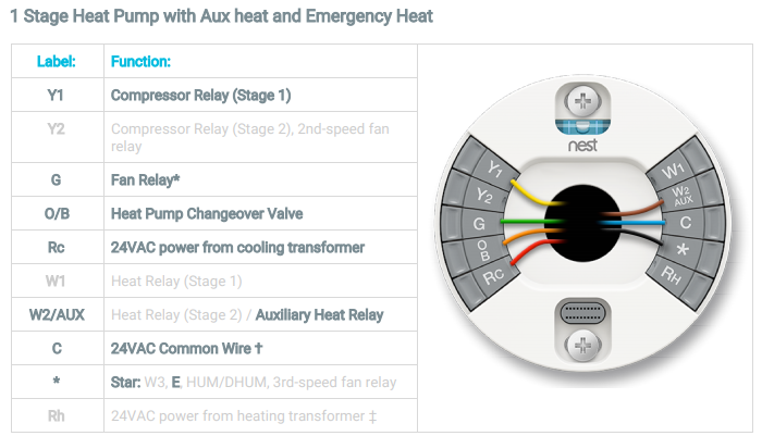
A single-stage heat pump typically connects one of the compressor relay connectors (Y1) for cooling. For heating, you will connect the AUX terminal for auxiliary heat and the * connector for emergency heat (E). In total, this setup will have seven wires connected.
- Y1: Compressor Relay (Stage 1)
- G: Fan Relay
- O/B: Heat Pump Changeover Valve
- Rc: 24VAC Power from Cooling Transformer
- W2/AUX: Heat Relay (Stage 2) / Auxiliary Heat Relay
- C: 24VAC Common Wire
- *: Emergency Heat (E)
2nd Stage Heat Pump (6-Wire Diagram)
For a two-stage heat pump, both the Y1 and Y2 connectors will have wire connections. In total, you should expect to see six wires connected as outlined below.
- Y1: Compressor Relay (Stage 1)
- Y2: Compressor Relay (Stage 2)
- G: Fan Relay
- O/B: Heat Pump Changeover Valve
- Rc: 24VAC Power from Cooling Transformer
- C: 24VAC Common Wire
2nd Stage Heat Pump with Auxiliary Heat (7-Wire Diagram)
This 7-wire configuration is for a two-stage heat pump with auxiliary heat. In this setup, both the Y1 and Y2 wires will be connected, along with a wire going into the W2/AUX connector.
- Y1: Compressor Relay (Stage 1)
- Y2: Compressor Relay (Stage 2)
- G: Fan Relay
- O/B: Heat Pump Changeover Valve
- Rc: 24VAC Power from Cooling Transformer
- W2/AUX: Heat Relay (Stage 2) / Auxiliary Heat Relay
- C: 24VAC Common Wire
Wiring Diagrams for Dual Fuel Systems
Dual fuel systems offer a strategic advantage by utilizing a heat pump for efficient heating during mild weather. However, in extreme temperatures, alternative heating sources kick in to provide the necessary warmth. It’s important to note that the efficiency of a heat pump decreases as outdoor temperatures drop. Wiring these dual fuel systems is straightforward; you simply add the connections for the alternative heating source as shown in the following diagrams.
1st Stage Heat Pump with 1st Stage Heating (6-Wire Diagram)
In this dual fuel configuration, all necessary wires for a single heat pump are connected, plus an additional wire connected to the W1 terminal for alternative heating. The total number of wires in this setup is six.
- Y1: Compressor Relay (Stage 1)
- G: Fan Relay
- O/B: Heat Pump Changeover Valve
- Rc: 24VAC Power from Cooling Transformer
- W1: Heat Relay (Stage 1)
- C: 24VAC Common Wire
2nd Stage Heat Pump with 1st Stage Heating (7-Wire Diagram)
In a dual fuel system with a heat pump and a single-stage heating system, there will be a total of seven wires connected. The wiring follows the same principles as for a 2nd stage heat pump, with the additional wires for the single-stage furnace included.
- Y1: Compressor Relay (Stage 1)
- Y2: Compressor Relay (Stage 2)
- G: Fan Relay
- O/B: Heat Pump Changeover Valve
- Rc: 24VAC Power from Cooling Transformer
- W1: Heat Relay (Stage 1)
- C: 24VAC Common Wire
1st Stage Heat Pump with 2nd Stage Heating (7-Wire Diagram)
In this configuration, the wiring includes all necessary connections for the heat pump as well as the W2/AUX connector for the second stage heating.
- Y1: Compressor Relay (Stage 1)
- G: Fan Relay
- O/B: Heat Pump Changeover Valve
- Rc: 24VAC Power from Cooling Transformer
- W1: Heat Relay (Stage 1)
- W2/AUX: Heat Relay (Stage 2)
- C: 24VAC Common Wire
2nd Stage Heat Pump with 2nd Stage Heating (8-Wire Diagram)
This setup represents the most comprehensive dual fuel configuration, incorporating both a two-stage heat pump and a two-stage furnace. Consequently, this diagram has the maximum number of connections, integrating all wires from both systems.
- Y1: Compressor Relay (Stage 1)
- Y2: Compressor Relay (Stage 2)
- G: Fan Relay
- O/B: Heat Pump Changeover Valve
- Rc: 24VAC Power from Cooling Transformer
- W1: Heat Relay (Stage 1)
- W2/AUX: Heat Relay (Stage 2)
- C: 24VAC Common Wire
Wiring Diagrams for Fans
2-Speed Fans
The wiring for a 2-speed fan consists of only three wires. One wire connects to the G terminal for the first speed, and another connects to the Y1 terminal for the second speed. Refer to the diagram below for clarity.
- Y2: 2nd-Speed Fan Relay
- G: Fan Relay
- Rh: 24VAC Power from Heating Transformer
3-Speed Fans
For a 3-speed fan, four wires are connected to the terminals. In addition to the three wires used for the 2-speed fan, there is an additional wire connected to the * terminal for the third-speed fan relay. See the diagram below.
- Y2: 2nd-Speed Fan Relay
- G: Fan Relay
- *: 3rd-Speed Fan Relay
- Rh: 24VAC Power from Heating Transformer
Testing the System After Wiring is Complete
- Testing for Heating and Cooling After wiring the thermostat, it’s essential to test the system to ensure everything functions correctly.
- To Test for Cooling: Switch the thermostat to ‘cooling’ mode and adjust the temperature setting to a value lower than the current ambient temperature. Wait for at least five minutes to see if cold air begins to flow.
- To Test for Heating: Switch to ‘heating’ mode and set the temperature higher than the current ambient temperature. Again, wait for five minutes to check for warm air.
- Selecting Between Cooling and Heating:
- Press the thermostat ring to access the menu.
- Select the heating and cooling icon.
- Rotate the ring to choose between heat and cool, then press to confirm.
- Testing 2nd Stage or Auxiliary Heat To test the 2nd stage or auxiliary heat on a heat pump:
- Turn off the auxiliary lockout.
- Raise the temperature setting by 4°F in heat mode.
PDFs
FAQ
How do you identify a C-wire on Nest?
While most manufacturers designate ‘C’ as the common wire, some may use ‘B.’ Here’s how to identify it:
For Conventional Systems: If ‘B’ is connected to your current thermostat, it is the common wire. Connect it to the C terminal on the Nest.
For Heat Pump Systems: If both ‘B’ and ‘C’ are present, connect ‘B’ to the O/B terminal and ‘C’ to the C terminal. If both ‘O’ and ‘B’ are connected, connect ‘O’ to the O/B terminal and ‘B’ to the C terminal.
How do I set Nest auxiliary or compressor lockout?
To set lockout temperatures, your thermostat must be connected to Wi-Fi to monitor outdoor temperatures. By default, when the outdoor temperature is above 50°F, Nest will lock out auxiliary heating (but not the compressor).
To change the lockout settings:
Access the menu by pressing the ring.
Select ‘Settings’.
Choose ‘Equipment’, then select the heat pump.
How to fix Nest blowing hot air on cool and cold air on heat?
If your Nest thermostat has reversed heat and cool settings, you need to adjust the heat pump orientation:
Press the ring to bring up the menu.
Select ‘Settings’.
Choose ‘Equipment’.
Select ‘Heat Pump’.
In Summary
We hope this guide helps you successfully wire your thermostat and ensure your system operates correctly. If you encounter difficulties, it’s always best to consult a professional. Below is a quick reference table for wire connections based on system types.

I’m Alan William’s, the founder of SmartHeatSolution.com. I am from California, USA, I’m passionate about innovative heating technologies and their impact on our homes and businesses. With a background in electrican and home repair , I aim to make smart, energy-efficient heating accessible to everyone. When I’m not writing, I’m likely interested in all the thermostat brands and their new technnology. Thanks for stopping by!

![White Rodgers Thermostat Manual [Made Easy] 10 White Rodgers Thermostat Manual](https://smartheatsolution.com/wp-content/uploads/2024/09/Business-1-768x432.png)
